DISTRIBUTOR-FIRST SUPPLY PARTNER · SINCE 1999 Live · Pneumatic Automation System

SPC Company
Pneumatic Automation / Actuation / Rotary & Electric Actuators / Electric Actuator
Layer 04 · Actuation Performance · SMC
What it is

Electric Actuator

Compare tiers ↓

An electric actuator converts the rotation of an electric motor into precisely controlled linear or rotary mechanical motion. It does the same physical job as a pneumatic cylinder, push, pull, lift, press, slide, or rotate a load, but a motor turning a precision ball screw drives the motion instead of compressed air driving a piston. Because an encoder on the motor measures shaft position continuously, the controller always knows exactly where the actuator is. That is the defining difference: position is measured and controlled throughout the motion. The core body style is the rod type; a rod extends and retracts exactly as a pneumatic cylinder's rod does, which makes it a footprint substitute for a cylinder on an axis that needs precision. Inside the rod, the motor turns a ball screw and the screw drives a nut, and the rod attached to that nut travels with it. The screw's lead, how far the rod travels per motor turn, sets a force-versus-speed trade-off: a small lead delivers high thrust and fine resolution, a large lead delivers higher speed. What this buys an application is the ability to stop accurately at any point along the stroke, store and recall many target positions, press to a programmed and repeatable force, and return to a position within hundredths of a millimeter, none of which a pneumatic cylinder can do, since a cylinder stops reliably only at full extend or full retract. The trade-off is upfront cost, the need for a separate controller and electrical engineering, and reduced suitability for washdown and hazardous environments. An electric actuator is the right choice when motion has to be exact rather than simply complete; for a straightforward on/off motion, a pneumatic cylinder remains the correct, lower-cost answer.
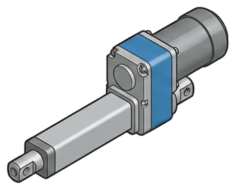
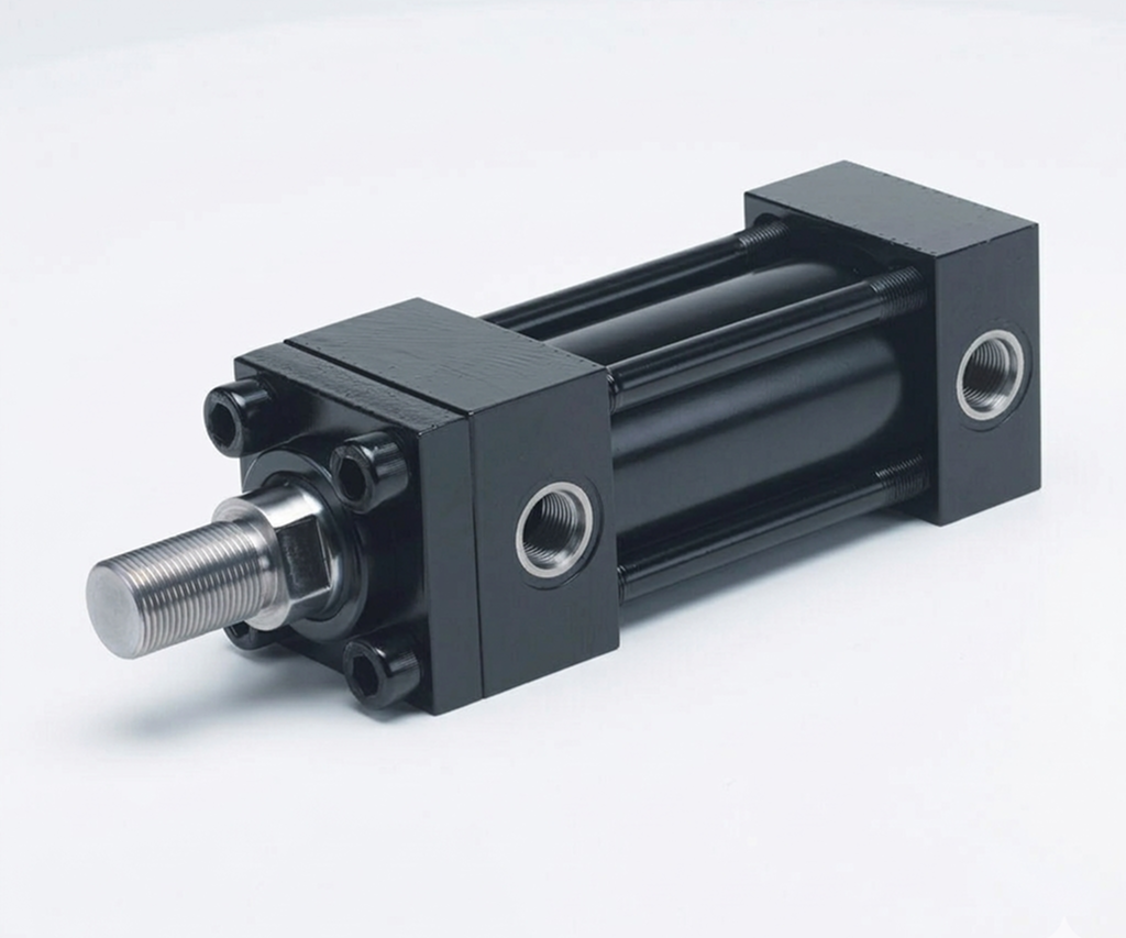
Pictorial Representative electric actuator
Electric Actuator — representative illustration
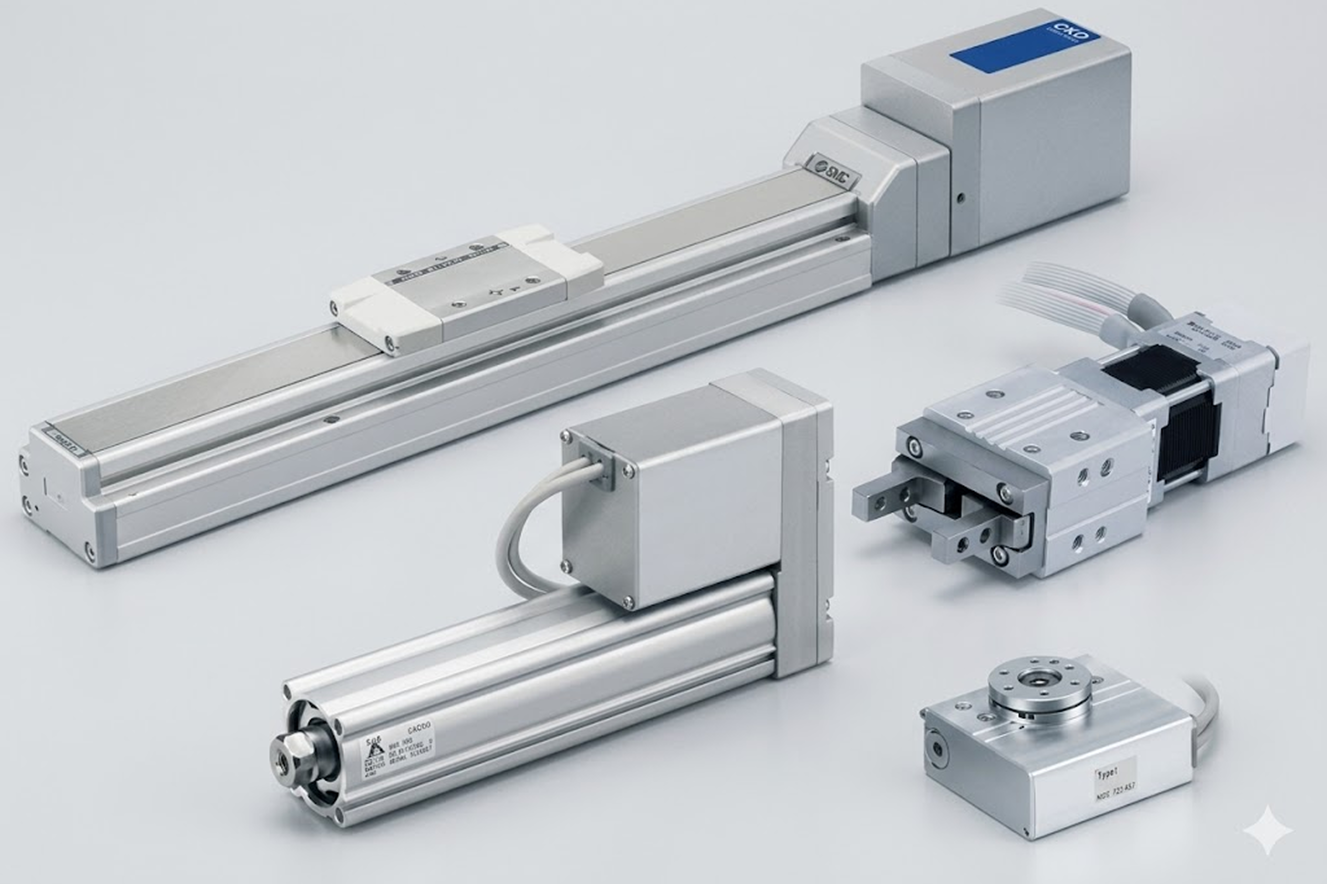
Real-world reference Representative electric actuator
Electric Actuator — representative product photo
Why it's needed

Why this matters.

When an electric actuator earns its premium, and when pneumatic is still the right call. Review the points below.

01 · Key point
It knows where it is.

An encoder reads motor-shaft position continuously, so the controller stops the rod at any point along the stroke, including full extend and full retract. Repeatability ±0.02 mm standard, ±0.01 mm on high-precision frames.

02 · Key point
It drops into the cylinder mount.

The Industry Leader tier rod-type matches typical ISO 15552 / NFPA mount geometry, usually a direct drop-in on an existing pneumatic axis. Swap valve + air lines for motor + encoder cables and the axis is now precision.

03 · Key point
Programmable force, not max pressure.

AC servo + ball-screw drive presses to a commanded force value, repeatable to ±1-3% of rated. Grippers handle delicate parts at low force and rigid parts at high force on the same cycle, pneumatic only grips at line pressure.

04 · Pro tip
Quote the controller on line two.

The controller is a required separate line item: most first-quote misses live here. Tiers: programless (panel-set), step-data (up to 64 PLC-callable positions), fieldbus (EtherNet/IP, EtherCAT, PROFINET). Match to the controls design.

05 · Where not to use
Simple on/off motion.

If the axis just needs full extend / full retract, electric is price-and-complexity overkill. → Stay with a pneumatic cylinder: cheaper, simpler, no controller, no electrical engineering line.

06 · Where not to use
Washdown or hazardous-location duty.

Mid-range IP-rated electric exists, but full washdown and ATEX (explosion-proof) territory is narrow and expensive. → Keep the axis pneumatic: cylinders survive wet and classified environments long-term where electric doesn't.

07 · Where not to use
Vertical lift without a motor brake.

Servos draw current continuously to hold a vertical load against gravity; power-fail = load drops. → Spec the integrated motor brake option on every vertical-axis install with meaningful load weight. Many premature failures trace back to skipped brake spec.

Key selection criteria

What we need to spec it right.

From the machine spec sheet to the part number. Answer what you know, leave the rest blank, and send.

04Choose your priority  ·  core differentiator

Whatever your lever — performance, value, or price — SPC has the right brand.

Pick the priority; the quote desk handles the cross-reference.

01 Performance 1 brand
Where it's used

Industries served.

Each industry below uses this product across the listed areas. Open an industry to see how it fits the rest of its system.

Also applies to Pneumatic-to-electric retrofits on legacy machines · The rod-type body style is the footprint substitute · Multi-position assembly fixtures · Programmable-force press operations · Precision positioning slides and stages · Electric grippers in robotic end-of-arm tooling · Energy-efficiency conversions on high-cycle production · Network-integrated motion control · Quiet-environment applications

Install · 6 critical steps

The things that matter on the first install.

Step 01
Qualify precision and capture load + orientation
Mid-stroke positioning, multiple stops, programmable force, or ±0.05 mm repeatability? If yes, electric. If just full extend / full retract, recommend pneumatic, electric for simple on/off is a price-and-complexity miss. Capture work load and mounting orientation; vertical capacity is always lower, and vertical installs require a motor brake for fail-safe holding (load drops on power-fail without one).
Step 02
Calculate thrust + choose ball-screw lead + choose body style
Required pushing force from the application with safety factor. Small lead = high thrust, fine resolution, slow. Large lead = lower thrust, coarser, fast. Most production-rate applications pick mid-range lead. Body style: rod type (footprint substitute for standard cylinder), guide-rod type (side-load), slider type (substitute for guided slide), miniature type, rotary table type, gripper type.
Step 03
Specify motor + encoder
Stepper motor: 24 VDC, lower cost, simpler integration, adequate for point-to-point. AC servo motor: higher speed, acceleration, pushing force; holds position under load with active control, required for precision force control, high-cycle production, or vertical hold. Incremental encoder = lower cost, requires homing move on power-up. Absolute encoder = higher cost, knows position at power-up, no homing, specify for any application where restart speed matters or homing motion would damage the application.
Step 04
Specify the controller tier
Programless = panel-set positions, no PC, no PLC (simple manual setup). Step-data = PLC-callable storage, up to 64 positions each with position/speed/acceleration/force. Fieldbus = plant-network integration (EtherNet/IP, EtherCAT, PROFINET). The controller is a separate required line item, always quote with the actuator. Most first-quote misses live here.
Step 05
Plan electrical integration before mechanical install
Install requires: 24 VDC power supply for steppers or AC servo power supply for servos, I/O wiring from controller to PLC, network cable if fieldbus, motor + encoder cables from actuator to controller. Plan cable routing, EMI (electromagnetic interference) shielding, and cable lengths up front. Electrical engineering for the install is a real labor line that pneumatic doesn't require; quote it.
Step 06
Document for service planning
Record actuator model, body style, ball-screw lead, motor type, encoder type, controller part number, brake option (if vertical), and cable lengths. Project service life at 5,000-10,000 km of travel; schedule lubrication at OEM intervals (typically every 1,000 km or 2,000 hours). Missed lubrication is the #1 preventable cause of electric actuator wear; plan PM on the calendar from day one.
Troubleshoot · top failures

Most returns trace to one of these causes.

Symptom
Most likely cause
Fix
Electric actuator not reaching commanded position.
Load exceeds rated thrust (most common, sizing didn't account for actual load); motor stalled on over-current (hard mechanical stop or seized mechanism); encoder fault (controller doesn't know actual position); ball-screw or guide-rod binding from contamination or wear.
Recompute load including dynamic / friction / process loads. Upsize if undersized. Check for mechanical obstruction; if none, load is over rated thrust. For encoder fault, check cable and controller diagnostic, replace if damaged. For binding, inspect ball-screw and guide-rod, clean and re-lubricate per OEM spec.
Position repeatability has degraded over time.
Ball-screw wear (expected after thousands of km of travel); ball-screw bearing wear; encoder calibration drift (rare); or load profile changed (heavier load, faster acceleration, more cycles per minute than the actuator was sized for).
Replace ball-screw assembly (Industry Leader tier lines offer field service kits). For load-profile changes, recompute and possibly upsize. For encoder drift, recalibrate per OEM procedure or replace.
Motor running hot.
Duty cycle exceeds motor rating (continuous when intermittent is rated, or higher cycle rate than rated); elevated ambient temperature; inadequate cooling clearance; load exceeds rated thrust (motor drawing higher current than designed).
Verify duty cycle against rating, if exceeded, upsize or de-rate to spec. Improve ventilation. For load over-rated, upsize. Continuous high-temperature operation degrades motor windings and shortens service life dramatically.
Vertical-load application drops the load when power fails.
No motor brake installed. Electric servos draw current continuously to hold a vertical load against gravity; power-fail = load no longer held.
Add motor brake (integrated brake option available on Industry Leader tier frames), engages automatically on power loss, holds the load mechanically. Mandatory on all vertical-axis electric actuators with significant load weight.
Controller communicates with PLC but actuator doesn't move.
Motor power supply not connected or failed (24 VDC or AC servo); motor cable damaged or disconnected; controller in fault state; PLC programming missing the move-command bit.
Check motor power supply first. Verify motor cable continuity. Reset controller per OEM procedure. Verify PLC program is actually commanding the move (communication with the controller alone does not command motion). For chronic communication-but-no-motion issues, work with the customer's electrical engineering on the integration.
Mechanical noise (clicking, grinding) from the actuator.
Ball-screw lubrication depleted (planned interval missed); ball-bearing wear in actuator body; debris in the ball-screw nut; debris in the linear guide rail on slider types.
Re-lubricate per OEM spec (use manufacturer-specified grease, substitutes degrade performance). If lubrication doesn't resolve, inspect for debris. For bearing wear, service-kit replacement on premium lines. Missed lubrication is the most common preventable cause of electric actuator failure: document the interval at install.

Get the right electric actuator on quote in 24 hours.

Send us the application — a specialist routes you to the correct tier with a configured part. Lead-times and pricing returned within one business day.

Open quote engine ↑