DISTRIBUTOR-FIRST SUPPLY PARTNER · SINCE 1999 Live · Pneumatic Automation System

SPC Company
Pneumatic Automation / Control & Valving / Valve Terminals & Regulators / IO-Link Valve Terminal
Layer 03 · Control & Valving Performance · SMC
What it is

IO-Link Valve Terminal

Compare tiers ↓

An IO-Link valve terminal is a smart valve manifold: multiple solenoid valves on one base with a single network gateway that reports data while routing air. Several stations mount side-by-side, share an internal supply and exhaust, and connect to the PLC (the machine's programmable logic controller) over one fieldbus cable instead of one wire bundle per valve. The gateway streams continuous diagnostics, per-valve cycle count, valve state confirmation, solenoid coil current, supply voltage health, manifold temperature, into the PLC, the SCADA, the MES, or a historian. This is the bridge component between traditional pneumatics and Industry 4.0 / IIoT (Industrial Internet of Things): the right answer whenever a customer is moving toward a smart factory, predictive maintenance, or remote diagnostics, and equally valid as a pure wiring-reduction play on a machine with many valves.
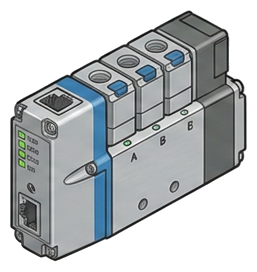
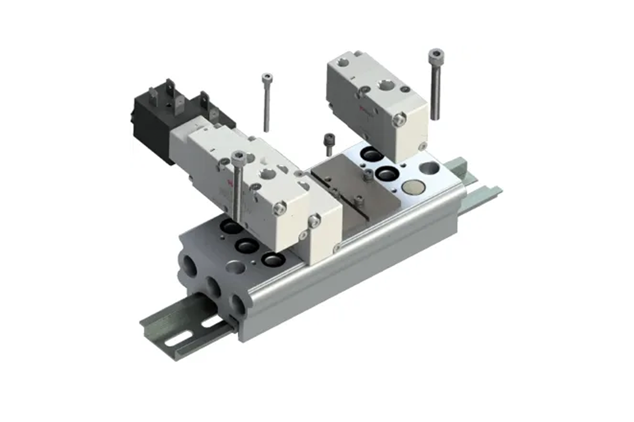
Pictorial Representative io-link valve terminal
IO-Link Valve Terminal — representative illustration
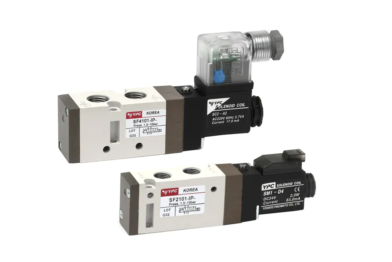
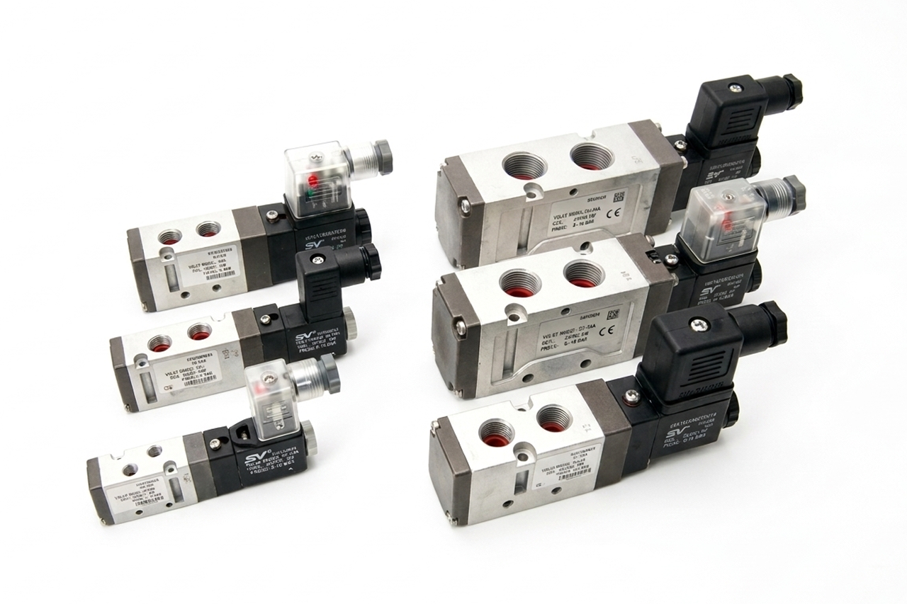
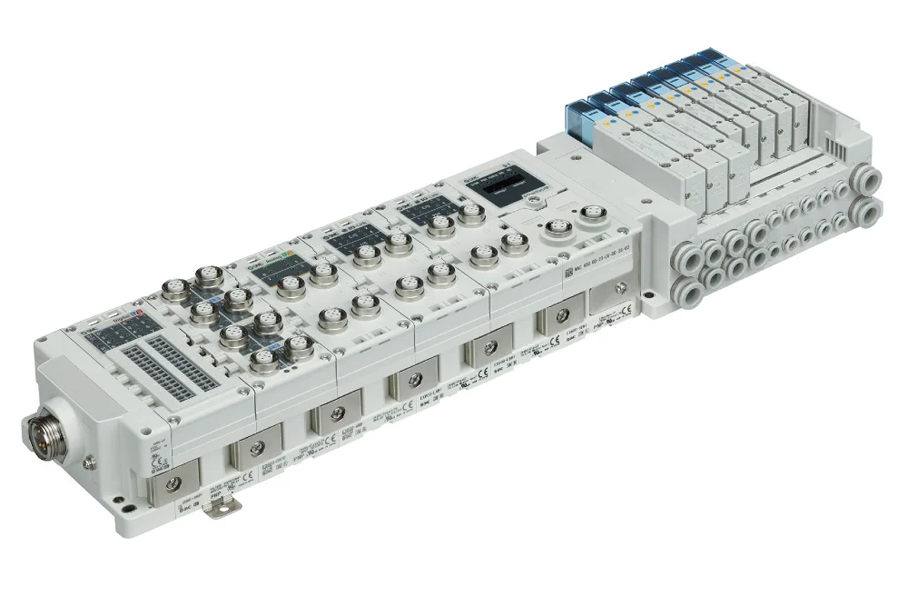
Real-world reference Representative io-link valve terminal
IO-Link Valve Terminal — representative product photo
Why it's needed

Why this matters.

When the IO-Link valve terminal is the right call, and when to spec something else. Review the points below.

01 · Key point
One cable replaces a wire loom.

A conventional 16-valve manifold runs a 32-conductor bundle to the PLC. The IO-Link gateway collapses that to a single 3-wire IO-Link cable or one industrial Ethernet line, large immediate labor savings on fresh installs, larger on retrofits.

02 · Key point
Per-valve diagnostics in real time.

Cycle count, shift confirmation, coil current, supply voltage, manifold temperature, downstream pressure where integrated. Maintenance sees a valve approaching its cycle-life rating weeks before failure: replace on the next scheduled changeover, not during an unplanned line stop.

03 · Key point
Shared gateway hosts more devices.

The same gateway hosts IO-Link sensors and switches: vacuum, pressure, position. One network, one cable, one diagnostic feed for valves and sensors combined. Each added endpoint compounds the original deployment.

04 · Pro tip
Match fieldbus protocol to the PLC.

The gateway is firmware-locked to ONE protocol. EtherNet/IP for Allen-Bradley / Rockwell, PROFINET for Siemens, EtherCAT for motion-heavy machines, DeviceNet / Modbus TCP for legacy. Get the confirmation in writing from the controls engineer; Rockwell plants sometimes run PROFINET on inherited Siemens lines.

05 · Where not to use
Safety-rated functions.

IO-Link is not a substitute for safety pneumatics. Applications requiring ISO 13849 PLd or PLe need dedicated rated hardware. → Route safety-rated functions through the customer's safety engineer; IO-Link handles standard automation only.

06 · Where not to use
Only 1–2 cylinders on the machine.

Gateway and terminal overhead doesn't pay back below roughly 8 valves on one machine. → Re-spec to inline solenoid valves for one- or two-valve installs where wire-bundle savings can't justify the gateway cost.

07 · Where not to use
No IIoT and no diagnostic appetite.

If the customer isn't doing predictive maintenance, MES integration, or cloud monitoring AND isn't buying on cable-savings, the diagnostic value goes latent. → Re-spec to manifold sub-base valve on the ISO 5599/15407 standard so a gateway-module swap can field-upgrade later.

Key selection criteria

What we need to spec it right.

From the machine spec sheet to the part number. Answer what you know, leave the rest blank, and send.

04Choose your priority  ·  core differentiator

Whatever your lever — performance, value, or price — SPC has the right brand.

Pick the priority; the quote desk handles the cross-reference.

01 Performance 1 brand
Where it's used

Industries served.

Each industry below uses this product across the listed areas. Open an industry to see how it fits the rest of its system.

Also applies to Existing-machine retrofits · Bridge-to-IIoT pilot deployments

Install · 6 critical steps

The things that matter on the first install.

Step 01
Confirm fieldbus protocol against the customer's PLC before unpacking
The gateway is firmware-locked to one protocol; EtherNet/IP, PROFINET, EtherCAT, DeviceNet, Modbus TCP. Wrong protocol = return shipment and project delay. Get the confirmation in writing from the customer's controls engineer; do not assume from PLC brand alone.
Step 02
Verify station count and per-station function code against the machine drawing
Each station's function (5/2 single solenoid, 5/2 double solenoid for memory-state, 5/3 closed-center, 3/2) is configured at the gateway level; physical valves must match configured functions. A 5/2 double-sol on a station configured as 5/2 single will not behave as expected on power loss. Cross-check as-shipped configuration against the machine cylinder list before powering on.
Step 03
Match coil voltage and verify available current for total coil count
24 VDC is standard. The 24 V supply feeding the gateway must deliver enough current for ALL coils that can be energized simultaneously; a 16-valve manifold at 200 mA per coil needs 3.2 A of headroom in burst conditions. Undersized supplies cause droop on simultaneous-firing events and create intermittent misfires that are confusing to diagnose.
Step 04
Mount with the IP rating you selected
Panel-rated terminals go in sealed enclosures; IP67 on-machine terminals can be exposed but must have correctly installed sealed connectors and cable glands. Verify the gland is rated for the cable diameter and is torqued to spec, undersized glands let water past the seal. Mixing a panel-rated unit on an exposed machine is a warranty failure.
Step 05
Configure the gateway with the IODD file in the PLC IDE
IO-Link devices ship with an IODD (IO Device Description) file: an XML or vendor-specific format that the PLC IDE imports to expose the device's parameters and diagnostics to the PLC programmer. Without the IODD, the device is just a generic IO-Link slave with no diagnostic data accessible. Download the IODD from the manufacturer (usually free) and import it before commissioning.
Step 06
Verify each station individually before connecting cylinders
Use the gateway's manual-override or PLC test-mode to fire each station one at a time, no cylinder attached, and confirm the valve shifts audibly and the cycle count increments on the PLC display. Catches wiring errors and configuration errors on the bench, before connecting cylinders where a wrong-station fire could damage equipment.
Troubleshoot · top failures

Most returns trace to one of these causes.

Symptom
Most likely cause
Fix
Gateway will not connect to the PLC network
Protocol mismatch (wrong gateway protocol for PLC, OR right protocol but wrong cycle time), OR IP address conflict, OR cable/connector failure, OR the PLC project doesn't have the gateway configured in its network topology.
Verify protocol match by reading the gateway label against the PLC IDE configuration. Check the gateway's IP address, many ship with a default that must be changed before adding to the network. Verify cable continuity. Confirm the gateway is added to the PLC project's topology and the EDS / GSD / ESI file (the protocol-specific device description) is loaded.
Valves fire correctly but don't appear in PLC's IO-Link diagnostic data
Missing or incorrect IODD file for those stations (#1 cause, basic firing works because IO-Link is layered; diagnostic layer requires the IODD), OR gateway firmware doesn't support the valve's IO-Link version, OR diagnostic data filtered at the PLC level.
Import the correct IODD into the PLC IDE. Verify gateway firmware against the valve-series compatibility matrix. Check PLC tag-mapping for diagnostic variables, they may be defined but not mapped to an HMI or historian.
Cycle count doesn't increment when a valve fires
Valve is firing on the override or bench-test path, not through the IO-Link command path (cycle counters only track IO-Link-commanded firings on most designs), OR diagnostic update rate is too slow to catch fast-firing valves, OR diagnostic memory has been reset and is rebuilding.
Verify the valve is being commanded through the IO-Link path, not manual override. Adjust the diagnostic update rate in gateway configuration. If just reset, allow several cycles to confirm incrementing.
Power-up
s one or more valves to fire briefly Cause: Gateway's default safe-state on power loss is set incorrectly (some gateways default to firing all 5/2 single-sols on startup until PLC takes control; a config setting changes this), OR the IO-Link master sends commands during initialization that the gateway interprets as fire commands.
Configure the gateway's safe-state on power loss to "all valves de-energized." Verify the PLC startup sequence doesn't send fire commands until after the application is fully initialized.
Integrated pressure sensor data is noisy or unstable
Sensor wiring loose at the manifold (common in vibration-prone installs), OR sensor failing, OR analog input scaling wrong on the gateway, OR real pressure pulsation in the supply line that the sensor is correctly reporting.
Reseat the sensor connection. Verify the sensor with a known pressure source. Check analog scaling against the sensor's datasheet. If correctly reporting real pulsation, address upstream pulsation (regulator droop, accumulator sizing).
Customer wants to add three more stations a year after install
Field-expansion wasn't planned. Most IO-Link terminals are field-expandable to the manifold's maximum if spare positions are available.
Check the spare-station configuration. If positions exist, expansion is a few minutes; add valves, update gateway configuration in the PLC IDE, push updated IODD config to the gateway. If no spare positions, the upgrade may require a new manifold base.

Get the right io-link valve terminal on quote in 24 hours.

Send us the application — a specialist routes you to the correct tier with a configured part. Lead-times and pricing returned within one business day.

Open quote engine ↑