DISTRIBUTOR-FIRST SUPPLY PARTNER · SINCE 1999 Live · Compressed Air System

SPC Company
Compressed Air / Generation / Air Compressors / Rotary Screw Compressor — VFD
Layer 01 · Generation Performance · Quincy Value · Ozen Air
What it is

Rotary Screw Compressor — VFD

Compare tiers ↓

A rotary screw compressor, VFD (variable frequency drive, an electronic motor controller that varies AC frequency, and therefore motor speed) is a continuous-duty industrial compressor whose airend speed tracks demand continuously. It sits in the generation layer at the head of the compressed air system, ahead of the receiver, dryer, filtration, and distribution piping. Sized 5 HP up to ~450 HP, three-phase, oil-injected, rated 100% duty.
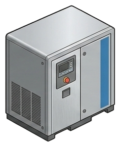
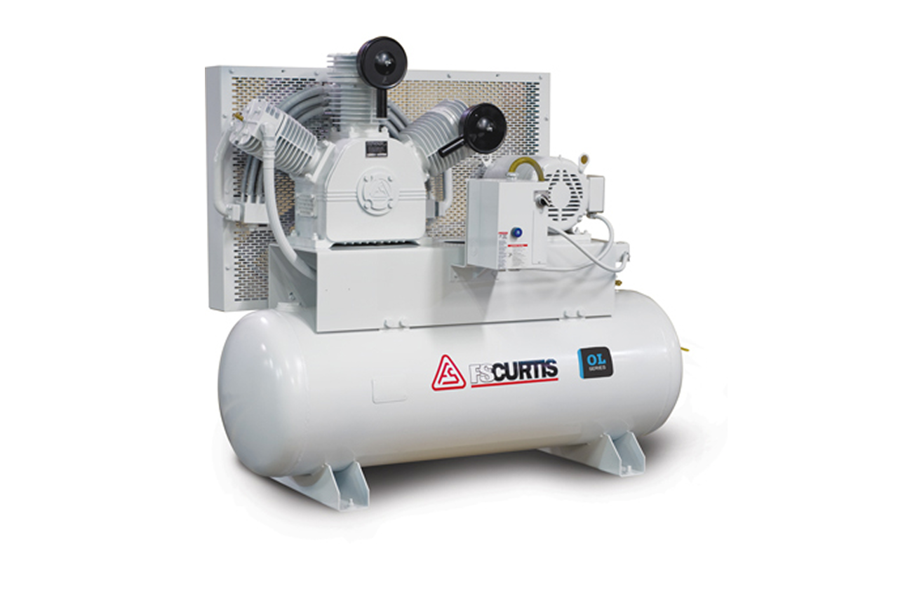
Pictorial Representative rotary screw compressor — vfd
Rotary Screw Compressor — VFD — representative illustration
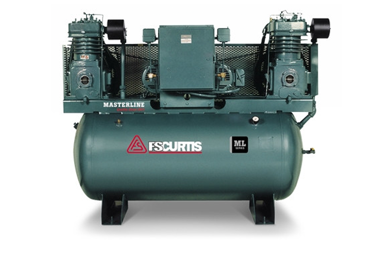
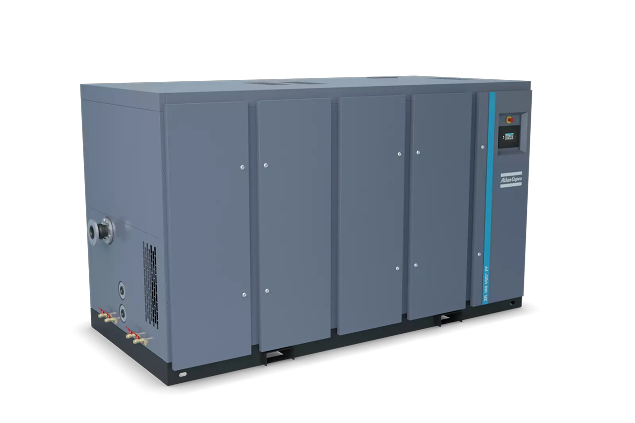
Real-world reference Representative rotary screw compressor — vfd
Rotary Screw Compressor — VFD — representative product photo
Why it's needed

Why this matters.

When a VFD rotary screw pays back fast, and when the inverter premium is wasted. Review the points below.

01 · Key point
Motor speed tracks demand.

The drive slows the airend when demand drops, so power draw follows air output roughly linearly, no unloaded motor burning 25-40% of full-load kW for zero CFM.

02 · Key point
25-50% off the electric bill.

Typical savings at sites with genuine demand variability. Payback runs 1-3 years on the $2-5K inverter premium for a 50 HP frame at $0.10/kWh.

03 · Key point
Holds pressure on one setpoint.

No load/unload band drift, system pressure stays steady instead of swinging 10-15 PSI. Every 2 PSI of unnecessary pressure costs ~1% in energy, a second dividend on top of demand matching.

04 · Pro tip
Qualify the demand profile first.

First question on every VFD quote: "tell me about your air-demand profile." Rule of thumb, VFD pays back when load sits below ~70% of rated output more than ~30% of run hours. Multi-shift, batch, and packaging plants almost always qualify.

05 · Where not to use
Flat continuous-process load.

A plant running steady at rated capacity 24/7 gets nothing from variable speed and pays extra for drive electronics. → Re-quote fixed-speed: save the customer $3-5K upfront; the honest call is the loyalty move.

06 · Where not to use
Hot rooms above 104°F at the drive.

Drive electronics derate above 104°F ambient and fault around 122°F. → Install cabinet AC, relocate the drive, or upsize so partial derate still meets demand. The #1 warm-weather complaint on VFD installs and 100% preventable.

07 · Where not to use
Crowded VFD feeders without mitigation.

Multiple drives on one feeder push THD (total harmonic distortion) past IEEE 519 limits: utility and ESG audit flags. → Quote a 3-5% line reactor with every drive; active harmonic filter at the panel on high-VFD-density plants.

RFQGuided system builder

Tell us about the shop. We size the system.

Answer a few plain questions and we build the full compressed air system for you: compressor, dryer, tank, filtration, and piping. No pricing here on purpose. SPC sizes, sources, and sends you an exact quote.

04Choose your priority  ·  core differentiator

Whatever your lever — performance, value, or price — SPC has the right brand.

Pick the priority; the quote desk handles the cross-reference.

01 Performance 1 brand
02 Value 1 brand
Install · 6 critical steps

The things that matter on the first install.

Step 01
Locate the compressor in the air train
Standard install order: VFD compressor → aftercooler (usually integrated) → wet receiver → refrigerated or desiccant dryer → pre/post filtration → distribution. The receiver is NOT optional just because the VFD modulates; it still buffers transient peaks and keeps the compressor from short-cycling on brief demand spikes.
Step 02
Verify three-phase service
VFDs need three-phase power matched to drive input voltage (480V standard in North America). Single-phase or wrong-voltage installs are non-starters. Have the electrician verify panel capacity for inrush + continuous load + 25% safety margin.
Step 03
Drive cabinet temperature
Drive electronics derate above 104°F ambient and most fault around 122°F. Mount the compressor in a cool location, or install cabinet AC, or move the drive to a separate enclosure if the compressor room runs hot in summer. This is the #1 warm-weather complaint on VFD installs and 100% preventable.
Step 04
Address harmonics on multi-VFD sites
A single VFD on a healthy feeder is usually fine. Multiple VFDs can push THD (total harmonic distortion) past IEEE 519 limits, which utilities and corporate sustainability audits will flag. Quote a 3% or 5% line reactor with every VFD as standard practice; active harmonic filters at the panel for high-VFD-density plants.
Step 05
Commissioning: set minimum and maximum speed
The drive has parameters for minimum operating frequency (typically 25-30 Hz) and maximum (60 Hz in the US). Set per OEM rating; running below minimum stresses airend bearings. Document dewpoint, pressure setpoint, and baseline kWh draw at commissioning so future drift is measurable.
Step 06
Document the service cadence
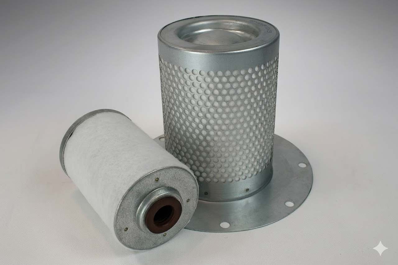
Annual oil change, oil/intake/separator filter change at hour intervals, drive cabinet filter cleaning every 6 months, thermal scan of the drive at annual PM. Hand the customer the schedule + SPC part numbers at install, preventive cost is a fraction of a drive replacement.
Troubleshoot · top failures

Most returns trace to one of these causes.

Symptom
Most likely cause
Fix
Drive faults on overcurrent or overload.
Mechanical binding in the airend (bearing wear, oil viscosity wrong for ambient), fouled intake filter raising load, or drive parameters set incorrectly during a recent service event.
Check airend bearings and oil, VFDs are unforgiving of mechanical drag because the drive sees current spikes immediately. Verify intake filter is clean. Confirm drive acceleration and current-limit parameters match the OEM commissioning sheet.
System pressure drifting outside setpoint.
Drive not modulating fast enough to match demand swings, pressure transducer drifted out of calibration, or demand exceeds compressor capacity at current speed range.
Verify with a calibrated test gauge that the transducer matches actual line pressure; replace if drifted. Check the drive's PI tuning parameters against the OEM sheet. If demand truly exceeds capacity, add storage or a second compressor.
Drive cabinet trips on overtemperature.
Ambient exceeds derating point (104°F), cabinet ventilation filter clogged, or internal cooling fan failed.
Clean the cabinet ventilation filter (often missed at PM). Verify the cooling fan spins. Measure ambient on a hot day, if over 100°F, install cabinet AC or relocate the drive.
Expected energy savings not materializing.
Demand profile isn't actually as variable as estimated, system pressure setpoint was bumped up after install (every 2 PSI ≈ 1%), or system air leaks have grown to the point the compressor is constantly making air.
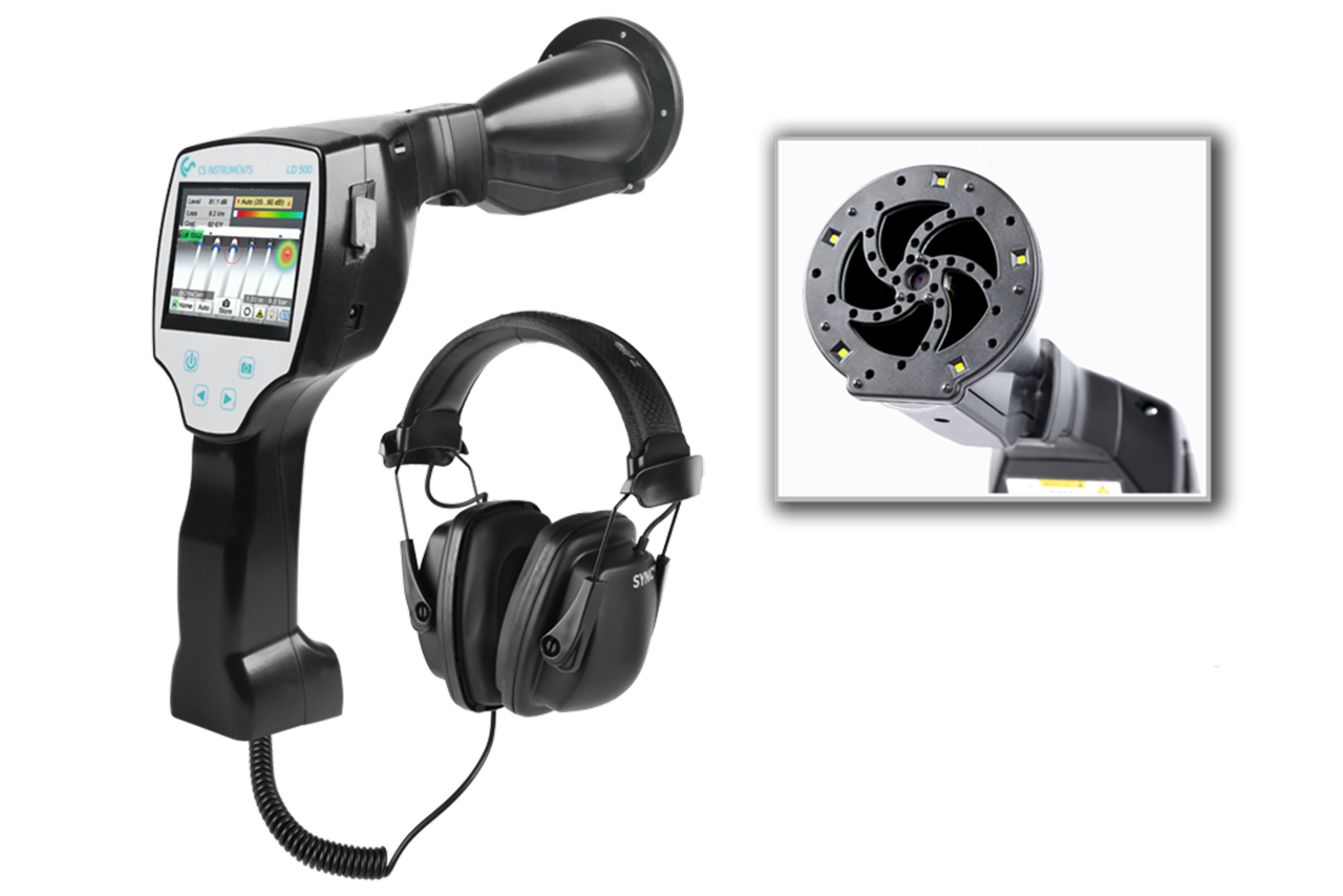
Pull the drive's actual kWh and run-hour data vs. pre-VFD baseline. If load is steadier than estimated, the VFD math doesn't apply, explain honestly. If setpoint crept up, ratchet it back. Run an ultrasonic leak survey and fix leaks, in most plants leak repair returns more energy than any other single intervention.
Motor bearing failure earlier than expected.
The drive's PWM output puts high-frequency common-mode voltage on motor windings, which can discharge through bearings as small electrical arcs and pit the races over time. Inverter-duty motors are designed for this; standard motors paired with a VFD are at risk.
At motor replacement, specify an inverter-duty motor with a shaft grounding ring. Industry Leader tier VFD compressors address this at the OEM level; field-applied VFD retrofits are where the failure shows up.

Get the right rotary screw compressor — vfd on quote in 24 hours.

Send us the application — a specialist routes you to the correct tier with a configured part. Lead-times and pricing returned within one business day.

Open quote engine ↑