DISTRIBUTOR-FIRST SUPPLY PARTNER · SINCE 1999 Live · Product System

SPC Company
What it is

Thermostatic Valve

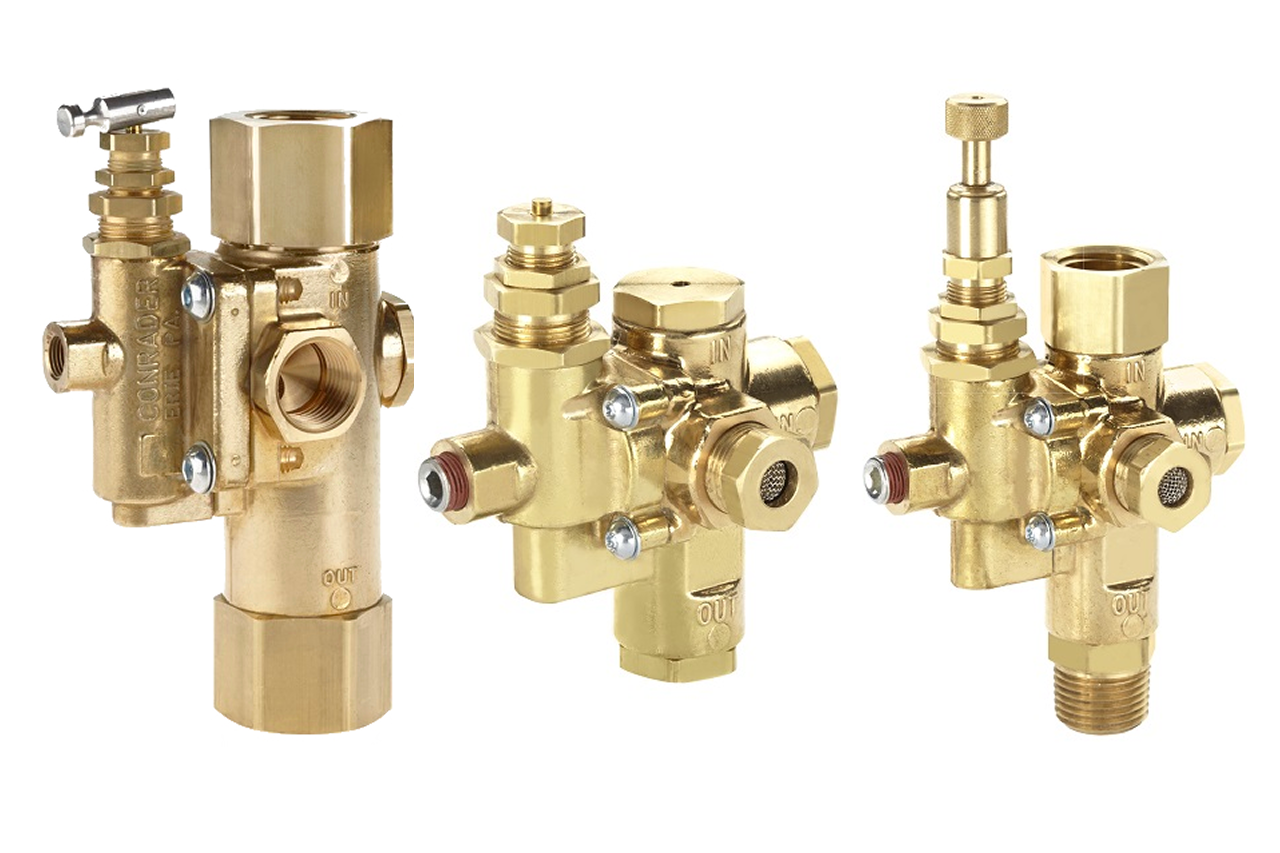
A thermostatic valve is the oil-temperature regulator inside a lubricated rotary-screw compressor, a temperature-sensing valve that routes circulating oil either through the oil cooler or around it on a bypass, blending the two streams so the air-end stays in its designed operating temperature band. The internal sensor is a wax-element or bimetal actuator that opens the cooler path as oil temperature rises and closes it as oil temperature falls. The valve is a wear part, not a scheduled consumable, replaced on failure or when temperature regulation drifts out of band, typically every 5-10+ years depending on operating temperature and oil condition. The defining variant is the setpoint temperature; a replacement must match the original setpoint exactly because the compressor was designed around its original band. It is selected by cross-referencing the OEM compressor make, model, HP, and setpoint temperature to an equivalent aftermarket part number.
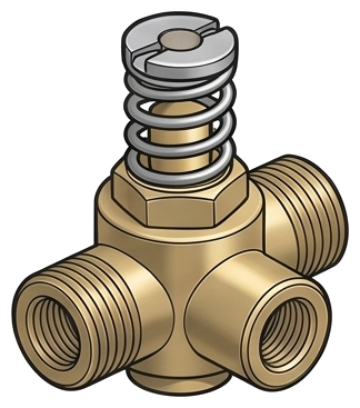
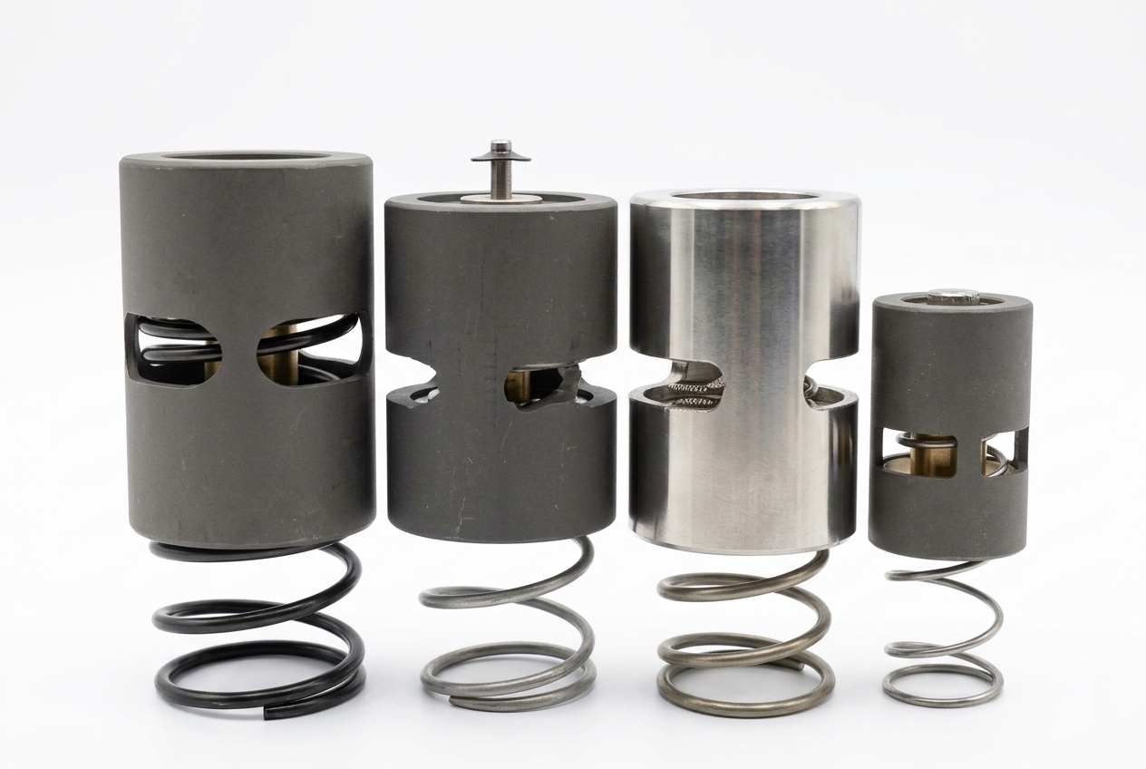
Pictorial Representative thermostatic valve
Thermostatic Valve — representative illustration
Real-world reference Representative thermostatic valve
Thermostatic Valve — representative product photo
Why it's needed

Why this matters.

When the thermostatic valve is the right call, and when the symptom belongs to the cooler or a different control valve. Review the points below.

01 · Key point
It holds oil within ±10°F of setpoint.

Wax-element or bimetal actuator blends cooler-return and bypass oil to hold the air-end at its designed band, regardless of ambient, load profile, or cooler effectiveness. Sits partially open at steady-state, mixing the two streams.

02 · Key point
It prevents both ends of the failure band.

Below ~140°F water condenses into the sump and emulsifies the oil into milky-coffee; above ~210°F oil oxidizes, varnishes the air-end, and loads the separator in months. The valve sits in the middle preventing both profiles.

03 · Key point
It crosses 40-60% under OEM list.

Leading-tier aftermarket cross-references to Atlas Copco, IR, Sullair, Quincy, Kaeser, Gardner Denver, Champion with US stock. $200-$800 vs. OEM at full list and multi-week lead: typically ships inside a $1,500-$4,000 bundled major-service event.

04 · Pro tip
Match the setpoint exactly.

Setpoint is the single most important spec, a 160°F valve and a 180°F valve are different parts for the same body and don't substitute. Read the stamp off the existing body or pull from the parts manual; common setpoints are 140°F, 160°F, 170°F, 180°F, 185°F. Wrong setpoint shifts the entire operating band off-design.

05 · Where not to use
Before eliminating the cooler side.

Fouled fins, failed cooler fan, or low cooling-water supply on water-cooled machines produce the same hot-running symptom. → Re-spec to a cooler clean or fan replacement if airflow and water-side checks haven't been done.

06 · Where not to use
"Running hot" with an unverified unloader.

A stuck-closed unloader runs the machine full-load 24/7 and dumps heat into the oil, looks identical to thermostatic-stuck-bypassed at the sump temperature gauge. → Re-spec to an unloader-valve cross if the compressor never reaches unload current.

07 · Where not to use
"Adjust to a higher setpoint" customer requests.

Customers sometimes ask for a hotter setpoint to "burn off the water", over-cooling and over-heating are both damaging and the compressor was designed around its original band. → Re-spec to the matching-setpoint cross unless an OEM service bulletin documents a change.

Key selection criteria

What we need to spec it right.

From the machine spec sheet to the part number. Answer what you know, leave the rest blank, and send.

Where it's used

Industries served.

Each industry below uses this product across the listed areas. Open an industry to see how it fits the rest of its system.

Also applies to Fixed-speed lubricated rotary-screw compressors, 25-200 HP plant range · 160-185°F · VFD (variable-frequency drive) rotary-screw compressors · Compressors in cold-ambient installations · more thermostatic failures per machine-year · Compressors with documented oil-temperature drift or high-temp trips · Compressors with water-in-oil findings on oil analysis · Compressors with accelerated separator loading · Aging installed-base machines past OEM warranty · 8-15+ years old · Multi-machine fleets on service-route agreements

Install · 6 critical steps

The things that matter on the first install.

Step 01
Confirm the cross-reference and verify the setpoint temperature
Pull the OEM part number and the original setpoint from the parts manual or the existing valve's body markings. Cross-reference to the aftermarket at the same setpoint, typically 140°F, 160°F, 170°F, 180°F, or 185°F depending on the OEM model. Verify body dimensions, port sizes, and mounting orientation before scheduling the service. The replacement must match the original setpoint exactly.
Step 02
Depressurize fully, lock out, drain the oil sump
Stop the compressor, vent the receiver and separator tank to 0 PSI, lock and tag the electrical disconnect. The thermostatic valve sits in the oil circuit and sees hot oil under pressure during operation, opening it hot or pressurized risks burns from oil splash. Wait for sump temperature to drop below safe handling (typically below 120°F). Most thermostatic valves cannot be removed without draining the oil; capture the drained oil per the customer's waste-oil plan.
Step 03
Remove the old valve and inspect the cooler and adjacent components
Disconnect the oil lines or remove the mounting bolts; on threaded NPT (National Pipe Thread Tapered) connections use a backing wrench to avoid stressing adjacent plumbing. Inspect the wax element or bimetal actuator on the removed valve, significant discoloration or carbon buildup on the sensing element indicates the compressor has been running hot for an extended period. Inspect the oil cooler and its passages while the lines are open; if the cooler is varnished or fouled, this is the moment to clean or replace it.
Step 04
Install the new valve at the matching setpoint, with correct flow orientation
Verify the new valve's setpoint marking matches the original before installation. Use new gaskets supplied with the cross-reference valve (do not reuse old gaskets; the oil circuit sees pressure and temperature cycling). Seat the valve in the correct flow-orientation per the body arrow markings or OEM diagram; reversed installation defeats the bypass function. Torque mounting bolts or threaded connections to OEM spec.
Step 05
Refill oil, prime the circuit, restart and watch through warm-up
Refill the sump with matched-grade synthetic compressor oil per OEM spec to the operating mark. If the cooler was drained or replaced, the cooler-side oil volume may need to be primed manually per the OEM service procedure. Verify there are no air pockets in the oil circuit before restart: an air pocket through the new valve can cause an erratic temperature reading and apparent valve failure on first start. Restart and watch oil temperature climb through warm-up: expected behavior is steady rise from ambient through setpoint, then stabilization within roughly 10°F of the setpoint at steady-state load.
Step 06
Run two full load/unload cycles and document
Confirm oil temperature stays within the normal band (±10°F of setpoint) through at least two load/unload cycles. A valve that lets temperature overshoot 20-30°F past setpoint or fails to reach setpoint at all in normal ambient is a bad install or a wrong cross, diagnose before completing the service. Document install date, part number, OEM cross, setpoint temperature, oil grade and quantity, and any other parts replaced. Schedule the next bundled major service on the customer's service-route calendar.
Troubleshoot · top failures

Most returns trace to one of these causes.

Symptom
Most likely cause
Fix
Oil sump temperature climbs continuously through warm-up and exceeds the normal operating band, with cooler fans confirmed running.
Thermostatic valve stuck bypassed, no oil reaching the cooler regardless of temperature. Less commonly: the cooler itself is internally fouled (varnish, sludge, debris) and not transferring heat even with full oil flow.
Confirm cooler airflow and cleanliness first (verify fan operation, fin cleanliness, water flow on water-cooled units). If the cooler is verified healthy, quote the thermostatic cross at matching setpoint. Bundle a fresh oil change since the existing oil has been running outside its temperature band.
Oil sump temperature stays well below the normal operating band in cold or normal ambient (e.g., running 110-130°F when setpoint is 170°F).
Thermostatic valve stuck full-flow to cooler, all oil bypassing the regulating element and going directly through the cooler regardless of temperature. Less commonly: the wax element has failed open, or (on bimetal valves) the bimetal has cracked.
Quote the cross-reference at the matching setpoint. Pull an oil sample at the same service to verify water content, running cold for an extended period typically condenses water into the sump and emulsifies the oil, requiring a full oil change rather than a top-up.
Oil temperature swings 20-30°F outside the normal band as the compressor cycles between load and unload.
Sluggish thermostatic response: the wax element or bimetal actuator is moving but lagging real-time temperature changes by minutes instead of seconds. Less commonly: undersized cooler for the duty cycle, or downstream demand pattern has changed such that the compressor sees more aggressive thermal cycling than designed.
Quote the cross-reference. If the new valve also shows sluggish response, look at cooler sizing and ambient conditions; some customers have added compressor load over years without upgrading cooling-side capacity.
Water visible in the oil at the sight glass; oil has a milky or coffee-with-cream appearance.
Oil running too cold for ambient humidity (thermostatic stuck full-flow to cooler), internal cooler leak on a water-cooled aftercooler letting cooling water into the oil, or, most rarely, a downstream system back-feeding water into the compressor.
Verify oil temperature first; if running cold, replace the thermostatic at matching setpoint. If oil temperature is in band but water is still appearing, inspect the cooler for internal leakage (pressure-test the water side against the oil side). Always do a full oil change, never a top-up, when water has emulsified into the oil.
Separator pressure differential climbing much faster than the typical service interval (reaching 10-12 PSI in months instead of a year).
Compressor running outside its designed temperature band, either too hot (oil oxidizing and depositing on separator media) or too cold (water emulsifying with oil and loading the separator with wet contamination). Either direction can be a thermostatic fault.
Pull oil temperature data over a typical operating day. If oil consistently runs above or below the normal band, the thermostatic is the root cause; a fresh separator without solving it will load just as fast. Quote the thermostatic cross plus the separator together.
New thermostatic valve installed but temperature symptom returned within weeks.
Wrong setpoint on the cross-reference (e.g., a 160°F valve installed where the OEM-original was 180°F), valve installed in reversed flow orientation, air pocket trapped in the oil circuit at install causing erratic temperature sensing, or the original symptom's root cause was the cooler rather than the valve.
Verify the installed valve's setpoint marking matches the OEM-original. Verify body orientation against the flow arrow. If both are correct, prime the oil circuit per OEM procedure to clear air pockets. If the symptom persists after all three checks, inspect the cooler, internal fouling or sizing issues can mimic thermostatic failure.

Get the right thermostatic valve on quote in 24 hours.

Send us the application — a specialist routes you to the correct tier with a configured part. Lead-times and pricing returned within one business day.

Open quote engine ↑