DISTRIBUTOR-FIRST SUPPLY PARTNER · SINCE 1999 Live · Pneumatic Automation System

SPC Company
Pneumatic Automation / Actuation / Vacuum End-Effectors / Vacuum Sensor / Switch
Layer 04 · Actuation Performance · SMC
What it is

Vacuum Sensor / Switch

Compare tiers ↓

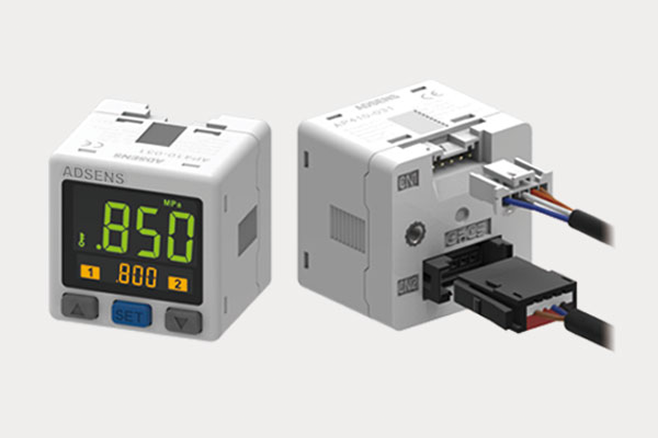
A vacuum sensor / switch is the verification device on a pick-and-place vacuum circuit; it monitors the live vacuum level and tells the PLC (programmable logic controller, the machine's control computer) whether the workpiece is actually gripped before the robot moves. It is one quarter of the vacuum end-effector sub-system: ejector + suction cup + vacuum sensor + replacement cup, sold and quoted together. The switch carries two adjustable set points, grip-confirm (releases the machine to move) and drop-detect (alarms a part lost mid-cycle), and mounts on the EOAT (end-of-arm tooling) plate or in a tee within 6 inches of the cup. Without a switch, a machine can complete its motion with no part on the cup and collide with downstream equipment.
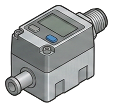
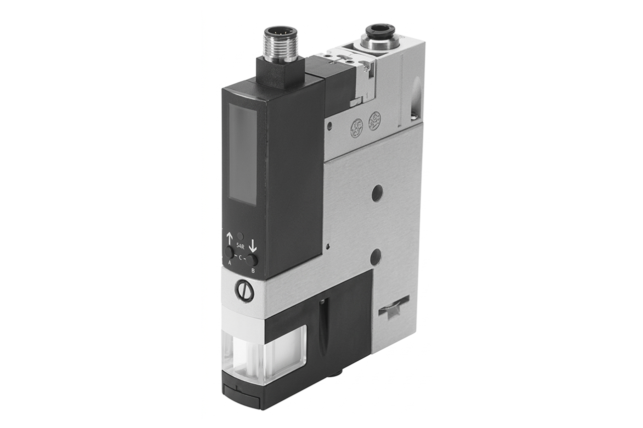
Pictorial Representative vacuum sensor / switch
Vacuum Sensor / Switch — representative illustration
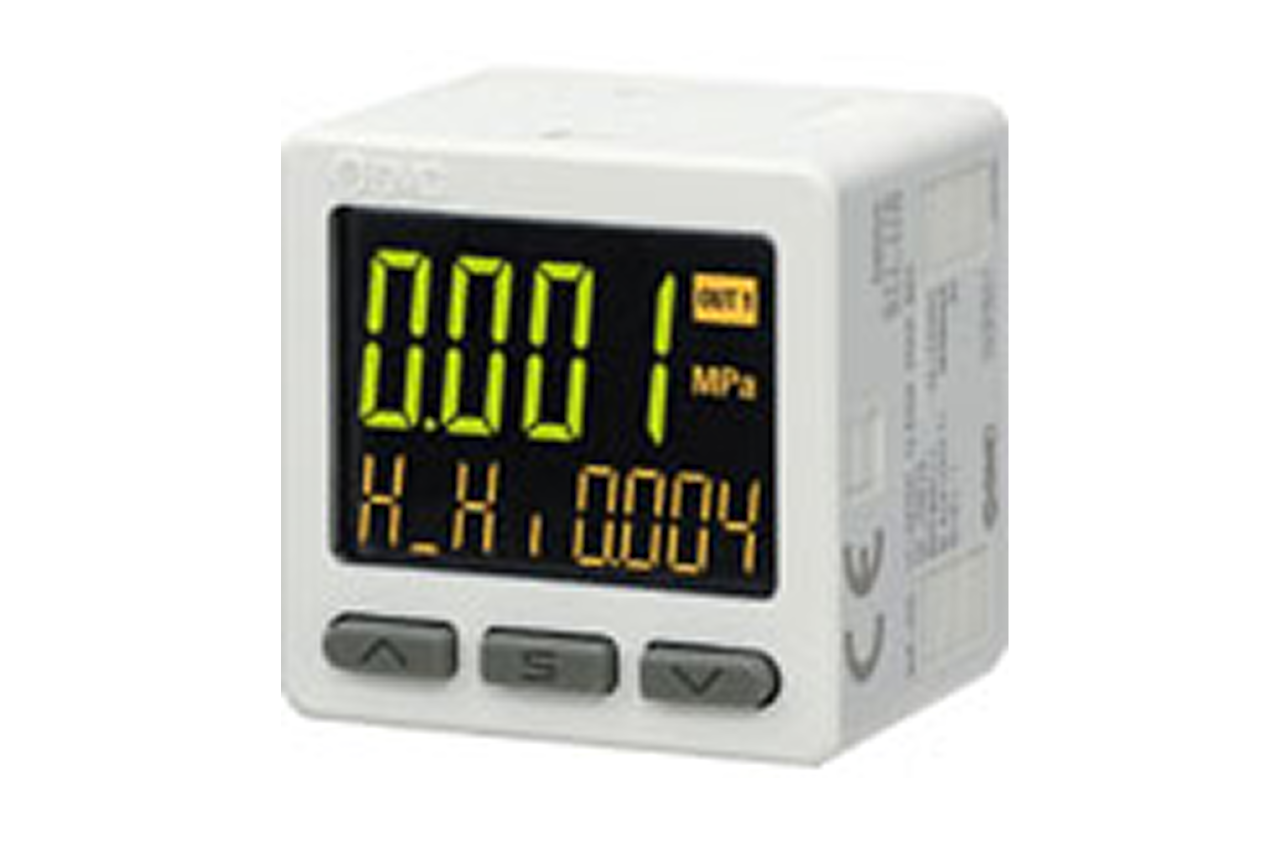
Real-world reference Representative vacuum sensor / switch
Vacuum Sensor / Switch — representative product photo
Why it's needed

Why this matters.

When to add vacuum verification, and where a switch alone won't save you. Review the points below.

01 · Key point
Verifies grip before motion.

A vacuum sensor / switch tells the PLC whether the part actually latched before the robot moves. Without it the machine operates on faith, and a lift with no part on the cup ends in a downstream collision.

02 · Key point
Two set points, two jobs.

Grip-confirm sits 10–15% below steady-state vacuum and releases the move command. Drop-detect sits 30–40% below and alarms a part lost mid-cycle. One device, two independent outputs into the PLC interlock.

03 · Key point
Set seal-integrity thresholds.

Switching response is a few milliseconds, fast enough to catch seal loss within one PLC scan cycle. Operating range typically –20 to –27 inHg (inHg = inches of mercury); set points must be re-verified whenever the workpiece changes.

04 · Pro tip
Match switching to the PLC.

NPN vs. PNP output polarity must match the PLC input card, the most common install-day mismatch. Digital display for field tuning, basic switched for cost, IO-Link for continuous 16-bit vacuum value to the network. Compound range when the circuit alternates vacuum with positive blow-off.

05 · Where not to use
Switch installed but not wired.

The most common configuration failure on retrofits: switch reads vacuum correctly, output never lands in the move-permission rung. The hardware is useless without the PLC logic. → Wire grip-confirm into move-permission and drop-detect into alarm/abort at every install.

06 · Where not to use
Mounted far from the cup.

A switch tapped at the ejector or manifold reads reach vacuum, not cup vacuum, false grip-confirm before the cup actually seals. → Mount within 6 inches of the cup on the EOAT block or in a tee on the cup line.

07 · Where not to use
Vacuum-only on a blow-off circuit.

A vacuum-only switch faults on positive pressure, and integrated blow-off blocks, test stands, and leak detectors cycle both. → Switch to compound-range variant for vacuum + positive pressure on the same line.

Key selection criteria

What we need to spec it right.

From the machine spec sheet to the part number. Answer what you know, leave the rest blank, and send.

04Choose your priority  ·  core differentiator

Whatever your lever — performance, value, or price — SPC has the right brand.

Pick the priority; the quote desk handles the cross-reference.

01 Performance 1 brand
Where it's used

Industries served.

Each industry below uses this product across the listed areas. Open an industry to see how it fits the rest of its system.

Also applies to Robotic EOAT on production pick-and-place · Test fixtures and inspection stands · Sheet-metal pick-and-place · Especially important on multi-sheet stack picking where double-blanking is a press-safety event. · Compound applications (vacuum + positive pressure on the same circuit)

Install · 6 critical steps

The things that matter on the first install.

Step 01
Confirm voltage, output type, and signal level against the PLC input card
NPN vs. PNP is the most common install-day mismatch. 12-24 VDC must match the PLC supply. For dual-output models, identify which output is grip-confirm and which is drop-detect on the wiring diagram. For IO-Link, confirm the master port supports the device's baud rate (typically COM3 / 230.4 kbps for vacuum sensors).
Step 02
Plumb the switch as close to the cup as practical
The switch reads vacuum at its install location, every fitting and inch of hose between the switch and the cup is volume that delays the reading. Mount on the EOAT block adjacent to the cup, or in a tee within 6 inches. Switches mounted on the manifold near the ejector show reach faster than actual grip and cause false grip-confirm at the PLC.
Step 03
Set the grip-confirm threshold first
Run a cycle without product to record the no-load vacuum ceiling. Run a cycle with product to record steady-state grip vacuum. Grip-confirm sits 10-15% below steady-state grip vacuum: high enough to confirm seal, low enough to tolerate variation. On a digital-display switch, use the tactile button; on IO-Link, set via the IODD (IO-Link device description file, the manufacturer's spec the PLC loads to know how to talk to the device) in the PLC.
Step 04
Set the drop-detect threshold second
Drop-detect sits 30-40% below steady-state grip vacuum, or just above the no-load ceiling. Low enough that normal grip variation doesn't false-trigger, high enough that an actual lost part is caught within milliseconds. Verify by manually breaking the seal during a cycle and confirming the PLC sees the drop signal within one scan cycle.
Step 05
Wire grip-confirm into the move-permission interlock
The move command in the PLC must be conditional on grip-confirm = true. Wire the switch's grip-confirm output to a discrete input and reference that input in the move-permission rung. Without this interlock, the switch is installed but ineffective, the most common configuration failure on retrofit lines.
Step 06
Wire drop-detect into the alarm / abort logic, then document set points
Drop-detect latches an alarm condition and aborts the current motion. Decide with the customer: drop = full machine stop (precision fixturing), drop = move complete + alarm (case packing), or drop = retry (high-cycle production). For IO-Link, load the IODD, confirm the sensor reports process value + status byte + diagnostic flags, set up HMI trending. Record grip-confirm and drop-detect set points on the machine drawing: undocumented set points are a multi-hour problem on every spare swap.
Troubleshoot · top failures

Most returns trace to one of these causes.

Symptom
Most likely cause
Fix
Switch shows grip-confirm but the machine still drops parts on the move
Grip-confirm set too low (false confirmation at marginal vacuum), switch installed too far from the cup (reading ejector vacuum, not cup vacuum), cup wear allowing intermittent seal loss after initial confirmation, or workpiece variation causing seal break mid-move.
Re-measure steady-state grip vacuum on a known-good pick and raise grip-confirm to sit 10-15% below that value, not at the no-load ceiling. Relocate the switch closer to the cup. Inspect cup contact face for wear or contamination. If variation is the cause, tighten drop-detect so any seal break is caught immediately.
False drop-detect alarms during normal cycles (line stopping unnecessarily)
Drop-detect set too tight (cutting into normal grip variation), supply pressure fluctuation causing vacuum dips, cup seating taking longer than the response window on porous workpieces, or workpiece variation pulling vacuum below threshold momentarily.
Loosen drop-detect; it should sit 30-40% below steady-state, not 10%. If margin is already correct, check supply pressure stability under cycle load. On porous surfaces, consider an ejector with higher suction flow to maintain vacuum against bleed-in. For variable workpieces, IO-Link with recipe-driven set points solves the variation problem.
Switch installed but the PLC isn't responding to grip-confirm or drop-detect signals
Wiring not connected to the PLC interlock (most common), wrong output type for the PLC input (NPN switch on PNP input or vice versa), voltage mismatch, or the PLC program doesn't reference the switch inputs in the relevant interlocks.
Verify wiring against the PLC schematic; confirm switch outputs are landed on the correct input addresses. Check NPN/PNP compatibility with the PLC card. Walk the PLC program with the customer's controls engineer and confirm grip-confirm is referenced in move-permission logic and drop-detect is referenced in alarm logic.
Digital display reading drifts or shows erratic values
Electrical noise on supply or signal lines, condensation or contamination inside the sensor housing (lower-IP model in wet environment), supply voltage out of spec, or sensor at end of life.
Verify supply voltage is stable and within rated range. Check shielding integrity on the cable run. Inspect housing for moisture ingress; replace with a higher-IP model (around IP65) if installed in a wet or washdown environment. If all electrical checks pass and the sensor still drifts, replace the unit.
IO-Link sensor not appearing on the network or not reporting data
IODD file not loaded in the PLC, wrong baud rate on the IO-Link master port, M12 cable not landed correctly (pin assignment varies between IO-Link and standard digital), or sensor configured for a different IO-Link revision than the master supports.
Load the manufacturer's IODD for the exact sensor model. Set the master port to the device's baud rate (typically COM3). Verify M12 cable pinout matches IO-Link spec. Confirm the master supports the sensor's IO-Link revision (1.1 vs. 1.0); newer sensors on older masters sometimes default to digital mode silently.
Set points reset themselves or drift between shifts
Operators adjusting set points on display models without authorization (most common), supply voltage cycling causing memory issue on lower-end sensors, or vibration on the EOAT loosening the tactile button.
Lock set points via the device's configuration mode, most digital-display switches have a lock that disables field adjustment. On IO-Link, set points are stored in the PLC and survive any device replacement. Document the locked set points and train operators that adjustment requires maintenance involvement.

Get the right vacuum sensor / switch on quote in 24 hours.

Send us the application — a specialist routes you to the correct tier with a configured part. Lead-times and pricing returned within one business day.

Open quote engine ↑