DISTRIBUTOR-FIRST SUPPLY PARTNER · SINCE 1999 Live · Compressed Air System

SPC Company
Compressed Air / Storage / Air Receiver Tanks / Vertical Receiver Tank
Layer 03 · Storage Performance · Manchester Tank Price · Morganton
What it is

Vertical Receiver Tank

Compare tiers ↓

A vertical air receiver is the default storage vessel for a compressed air system, a steel ASME (American Society of Mechanical Engineers) Section VIII Division 1 pressure vessel mounted upright on four legs, installed between the compressor and the distribution piping. Vertical orientation occupies the smallest floor footprint for a given volume, which is why it is the standard choice in most compressor rooms. The same tank serves as a wet tank (set after the compressor and aftercooler, before the dryer) or a dry tank (set after the dryer, before distribution), placement, not the vessel itself, defines the role.
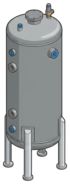

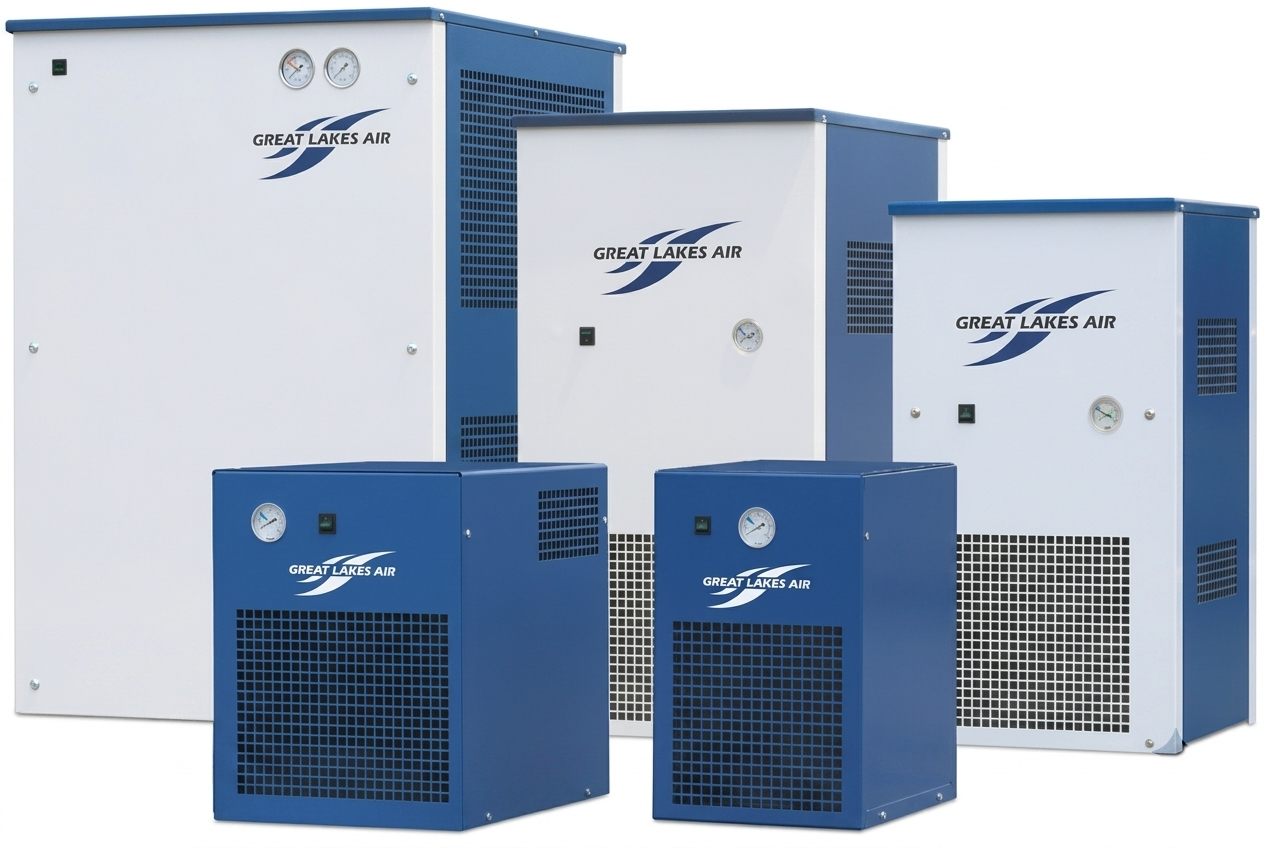
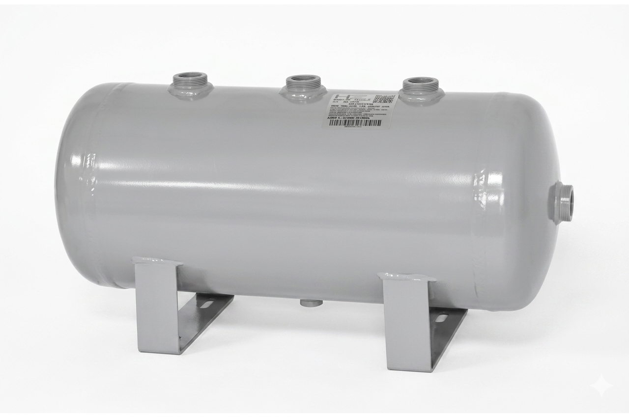
Pictorial Representative vertical receiver tank
Vertical Receiver Tank — representative illustration
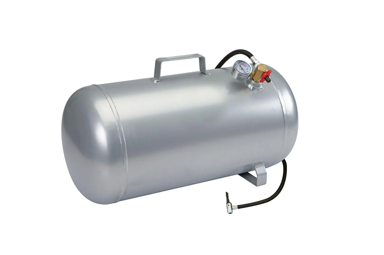
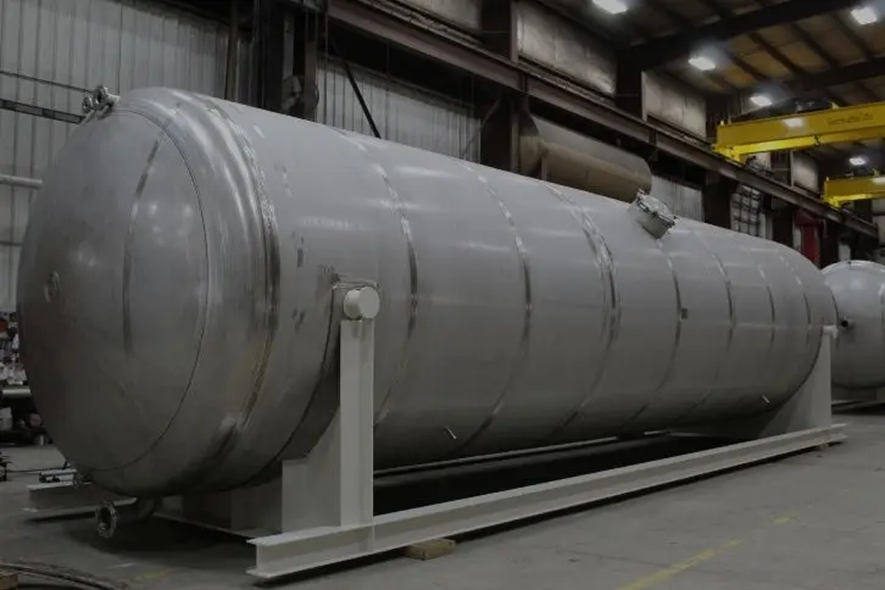
Real-world reference Representative vertical receiver tank
Vertical Receiver Tank — representative product photo
Why it's needed

Why this matters.

Why a vertical is the default storage call, and when it isn't. Review the points below.

01 · Key point
Smallest floor footprint.

A 1,060-gallon vertical takes 30-36 inches of floor diameter; the same gallons laid horizontal needs 20+ feet of length. The default storage choice in any compressor room with normal ceiling height.

02 · Key point
Stops air-end short-cycling.

Buffers demand surges so the compressor sees a slower-changing average. Short-cycling burns out air-end bearings, motor starters, and unloader valves in a fraction of their rated life; the receiver is the cheapest insurance against it.

03 · Key point
Single low-point drain.

Vertical column drops 60-80% of bulk water and oil out at one bottom drain on wet-tank service, maximum condensate residence time before the dryer sees it. Cleanest drain geometry of any tank format.

04 · Pro tip
Size by CFM, upsize between.

4-6 gal/CFM for fixed-speed compressors, 1-2 gal/CFM for VFD. Round up between catalog sizes, upsizing costs 15-20% on the tank and protects the air-end for its full service life.

05 · Where not to use
Low ceiling clearance.

A 1,060-gallon vertical stands 9-11 feet tall plus 8-12 inches of relief-valve riser above the crown. Under 8 feet of clearance to steel rules out most verticals above 240 gallons. → Re-spec to horizontal-receiver-tank.

06 · Where not to use
OEM skid-mount integration.

Packaged compressors above 40 HP often ship with the receiver lying under or behind the compressor on a shared skid. Vertical doesn't match the layout. → Re-spec to horizontal-receiver-tank coordinated with the OEM drawing.

07 · Where not to use
Above catalog envelope.

Above 1,550 gallons, above 200 PSI MAWP, non-standard geometry, or multi-chamber service, the catalog stops. → Re-spec to specialty-custom-pressure-vessel with engineered fabrication and full U-1A documentation.

Key selection criteria

What we need to spec it right.

From the machine spec sheet to the part number. Answer what you know, leave the rest blank, and send.

04Choose your priority  ·  core differentiator

Whatever your lever — performance, value, or price — SPC has the right brand.

Pick the priority; the quote desk handles the cross-reference.

01 Performance 1 brand
03 Price 1 brand
Where it's used

Industries served.

Each industry below uses this product across the listed areas. Open an industry to see how it fits the rest of its system.
Also applies to Standard industrial compressor rooms (the default install) · Wet-tank service (between compressor and dryer) · 60-80% of total system condensate · Dry-tank service (downstream of the dryer) · Reciprocating compressor pulsation dampening · Standard practice on any piston install above 5 HP. · Duplex and triplex compressor systems · Compressor upgrades and capacity expansions · Standby and emergency air storage

Install · 6 critical steps

The things that matter on the first install.

Step 01
Confirm sizing, ceiling clearance, and access route
Walk the compressor-room footprint before ordering. Verify floor space for the tank's legs, clearance for service access on all sides, and ceiling height under steel including the safety relief valve riser (8-12 inches above the top crown). Confirm the access route from the loading dock, a 1,060-gallon vertical is 9-11 feet tall and does not fit through every doorway upright.
Step 02
Prepare a level, load-rated pad
Concrete is standard, steel skid acceptable for OEM packages. Verify slab thickness and load capacity against the tank's wet weight (a 1,060-gallon at 150 PSI is over 2,000 pounds dry, more with condensate). Mezzanine or second-floor installs may need engineered floor reinforcement, in writing, before delivery.
Step 03
Set the tank plumb and anchor the four legs
Forklift or crane upright onto its legs. Check plumb with a level on two perpendicular axes. Bolt each leg through the manufacturer-supplied anchor holes; use bolts rated for the wet weight plus any seismic load factor required by local code. Do not weld the legs to anything: they must allow for thermal expansion and floor settlement.
Step 04
Install the ASME safety relief valve on its dedicated port
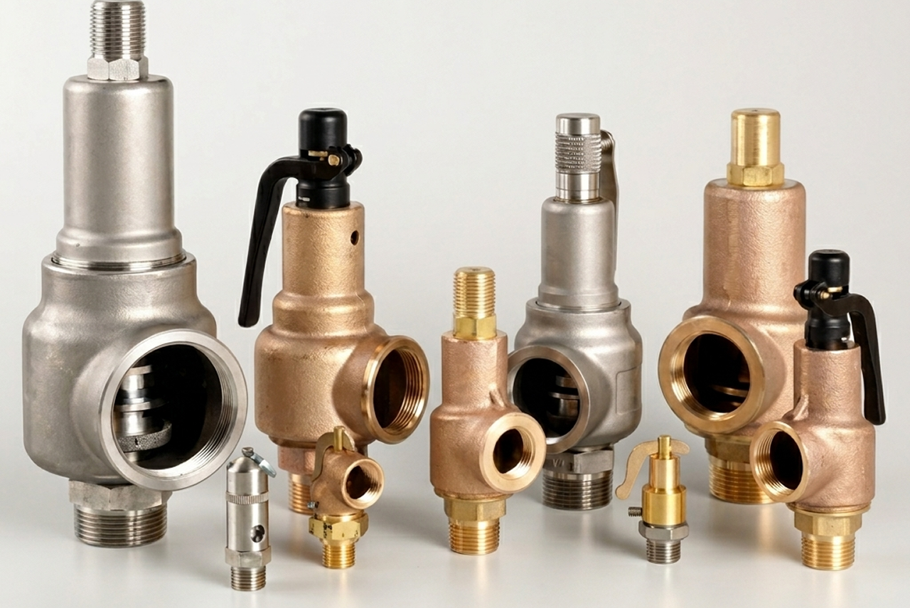
Thread the code-mandated relief valve into the dedicated safety port at the top of the tank, never on a tee, branch, or shared port. Verify the valve PSI matches the tank MAWP exactly, and verify SCFM capacity matches the compressor's full-load output. Discharge piping vents to a safe location away from personnel.
Step 05
Pipe inlet, outlet, and condensate drain
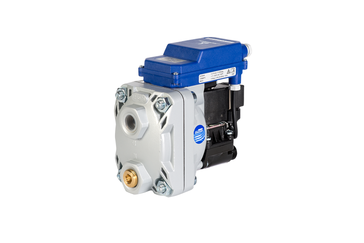
Use the manufacturer's port-size recommendations, reducing pipe size before the tank inlet throttles the compressor. Drain port at the tank bottom receives a zero-air-loss electronic drain or, at minimum, a timer drain, manual valves only as backup, never as the primary drain. Install an isolation ball valve upstream of the electronic drain for service access.
Step 06
Pressure-test, verify documentation, and schedule state inspection
Slowly bring the tank up to operating pressure and soap-check every joint (the tank was hydro-tested at the factory at 1.5x MAWP, field testing is for the joints, not the vessel). Confirm the U-stamp nameplate is visible and not painted over; record the National Board number in the customer's facility files. Add the tank to the customer's state-registered vessel list and schedule the first inspection.
Troubleshoot · top failures

Most returns trace to one of these causes.

Symptom
Most likely cause
Fix
Compressor short-cycling despite properly sized tank on paper
System leak rate exceeding compressor capacity at the cut-in setpoint, receiver isolation valve partially closed, pressure-switch band too narrow (under 10 PSI makes any compressor short-cycle regardless of tank size).
Audit for leaks during off-shift hours, short-cycling that disappears overnight is a leak problem, not a tank problem. Verify the isolation valve is fully open and the cut-in/cut-out band is 10-15 PSI wide. If storage is undersized, add a second vertical in parallel.
Condensate pooling under the tank or water leak at the drain
Drain valve seized or failing (corroded manual, failed timer solenoid, fouled zero-air-loss sensor), drain piping plugged with rust scale, or tank wall corrosion-through at the lowest point of the shell.
Open the drain manually, if water gushes out, the drain itself failed; replace it. If no water and the tank holds air, drain piping is plugged; break the line and clear it. Tank wall corrosion-through is a tank-replacement event, do not patch a pressure vessel.
ASME safety relief valve lifting periodically during normal operation
Compressor cut-out setpoint drifted above the valve's rated setting (pressure-switch drift over years), valve setpoint mismatched to MAWP, or valve fatigued from repeated lifts.
Verify the valve PSI matches the tank MAWP and the system runs below both. Check the pressure switch with a calibrated reference gauge. If the valve has been lifting repeatedly, the seat is damaged, replace it. Never adjust or disable an ASME safety relief valve under any circumstance.
Visible external rust streaks on the tank shell
Internal corrosion working through from the wet side, sometimes for years before becoming externally visible.
Visible external rust signals internal corrosion 9 times out of 10, by the time it shows outside, the inside has lost wall thickness. Schedule an ultrasonic thickness test by a qualified inspector; if remaining wall is below code minimum, the tank goes out of service immediately. Tanks over 20-25 years on wet service are typically replacement candidates, not repair.
Tank fails state pressure-vessel inspection
Missing or painted-over U-stamp nameplate, expired ASME safety relief valve, no current state registration, or visible shell damage (deep corrosion pits, weld cracks).
Painted-over nameplate can sometimes be carefully cleaned; missing nameplate is a tank-replacement event (the tank's identity lives on the nameplate). Expired relief valve is a same-day fix with a fresh ASME-rated valve sized to MAWP. Registration lapse is a paperwork fix with the state agency.
Water carryover downstream to the dryer or point of use
Tank drain failed or undersized for the moisture load (most common), wet-tank too small for adequate residence time, or upstream aftercooler failing (more water entering than designed for).
Verify the drain is operating on its rated cycle and discharging real condensate; replace with a zero-air-loss electronic drain sized to the actual condensate load. If the drain is fine, check aftercooler operation, air above 100°F entering the tank won't condense until it cools inside, overwhelming the drain.

Get the right vertical receiver tank on quote in 24 hours.

Send us the application — a specialist routes you to the correct tier with a configured part. Lead-times and pricing returned within one business day.

Open quote engine ↑